Pairwise Trajectory Management (PTM) is an Interval Management (IM) concept that utilizes airborne and ground-based capabilities to enable and benefit from airborne pairwise spacing capabilities in oceanic regions. The goal of PTM is to use airborne surveillance and tools to manage an “at or greater than” inter-aircraft spacing. Due to the precision of ADS-B information and the use of airborne spacing guidance, the PTM minimum spacing distance will be less than distances an air traffic controller can support with current automation systems that support oceanic operations. Ground tools assist the controller in evaluating the traffic picture and determining appropriate PTM clearances to be issued. PTM avionics provide guidance information that allows the flight crew to conform to the PTM clearance issued by the controller. The combination of a reduced minimum distance and airborne spacing management will increase the capacity and efficiency of aircraft operations at a given altitude or volume of airspace.
Studies indicate there will be continued growth in oceanic operations. Even with recent improvements to oceanic surveillance and communications systems, required separation standards in oceanic airspace are still large enough to cause aircraft operational inefficiencies. These inefficiencies include operating at other than their desired altitude, routes, and speeds for extended periods of time, flights being unable to operate on their desired routes, and flights required to change altitudes for crossing traffic. These system inefficiencies increase flight time and fuel burn.
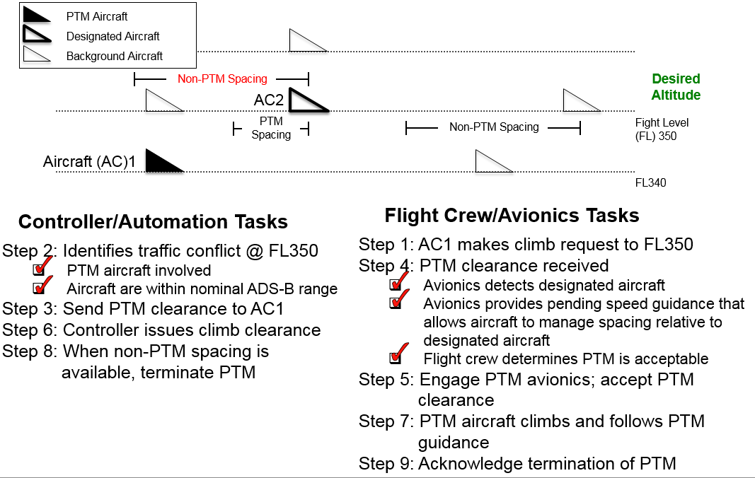
PTM is designed to enable operations that are not possible with current non-PTM, separation standards. These operations will be enabled by more efficient spacing assignments issued by controllers and managed by aircraft. The controller, using ground-based decision-support automation, issues a pair-specific PTM clearance to a PTM-equipped aircraft. When accepted, this clearance will allow the PTM aircraft to operate on the same flight level and track of the designated aircraft (the paired aircraft), or to cross the track of the designated aircraft with reduced spacing as compared to current non-PTM, separation standard minimums. The PTM clearance requires the flight crew of the PTM aircraft to use their ADS-B-enabled on-board Flight deck-based Interval Management (FIM) equipment to manage their spacing relative to the designated aircraft. The FIM equipment will provide speed guidance to ensure that the inter-aircraft spacing is no closer than the PTM minimum distance during the PTM operation. When the controller assesses (with ground automation system support) that a non-PTM separation standard has been achieved and the PTM operation is no longer required, the controller may terminate the PTM operation. The controller is not required to terminate the PTM operation as soon as non-PTM separation standards are available and may allow the PTM operation to continue for operational reasons.
The term “FIM equipment” is used here to refer to any avionics on board an interval management (IM) Aircraft that supports an IM application. The term “FIM equipment” does not imply any dedicated avionics or a specific avionics architecture.
PTM will support same track operations (typically found in oceanic organized track systems) and crossing track operations (typically found with oceanic user preferred routes). Due to the reduced PTM minimum spacing distance, the PTM aircraft may not be required to modify their current speed in many traffic crossing situations. PTM should save fuel and reduce delays by improving operations that increase time on an aircraft’s optimal trajectory (track and altitude). The airborne managed distance can allow for higher throughput and generally more efficient aircraft operations.
PTM may be employed, depending on local constraints and traffic characteristics, to support several different types of operations. For example, a PTM clearance could be used to resolve a short-term conflict (e.g., one aircraft climbing through the altitude of another) or could be used for an extended period of time (same track, same altitude).
The availability of a PTM resolution to a conflict does not necessarily make it the preferred option for the controller. PTM is not intended to take away the controller’s discretion in managing the traffic in their sector; PTM is simply an additional option for the controller to use as needed or desired.
There are also times when PTM is not an available option for the controller. One example of this is when the two aircraft are out of ADS-B range from each other (since the PTM aircraft must be receiving the ADS-B signal of the designated aircraft to accept the clearance and manage spacing). Additionally, other operational conditions may cause the flight crew to refuse the PTM clearance. This could include situations when PTM operations would require the flight crew to fly a speed that is faster or slower than the aircraft can maintain. In addition, certain traffic encounter geometries may prevent the availability of PTM to be used by either the controller or the flight crew (e.g., head on traffic encounter geometries).
Airborne PTM Human-Machine Interface (HMI)
Flight crews authorized to conduct PTM operations will require the use of a flight crew human-machine interface (HMI). Future implementations of an airborne HMI that will support PTM operations may be fully integrated, for example, with an aircraft’s primary flight display, navigation display, and multifunction control display unit. However, another possible implementation involves the flight crew HMI operating independently of other flight guidance and navigation displays. A non-integrated implementation of this type, which may be considered for retrofit installations, was designed and investigated at NASA LaRC.
NASA LaRC’s airborne PTM HMI consists of two primary hardware components – a side mounted display with a touchscreen interface and a 3 in x 3 in Configurable Graphics Display (CGD) located in the flight crew’s primary field of view. Possible locations for left-seat PTM HMI components within the flight deck are shown below.
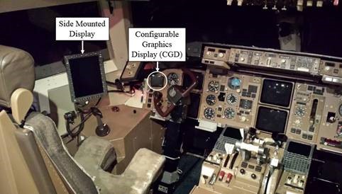
Pilots will use the side mounted display to review PTM clearances, engage or clear the PTM avionics, review displayed messages, indications, alerts, and as a situation awareness display tool. The CGD will display the PTM Guidance as well as indications that advise the flight crew to review the side mounted display. The CGD is located in the flight crew’s primary field of view and is intended to be the primary display used to ensure conformance with PTM Guidance during PTM operations. Controller-Pilot Data Link Communication (CPDLC) is also assumed to be in use during PTM operations.
As part of the iterative process used to design NASA LaRC’s airborne PTM HMI, researchers gathered data from 47 subject matter experts via a web-based survey, two workshops, and two sets of multi-session focus group activities. Additionally, the contents of two key references were carefully considered: RTCA minimum operational performance standards (MOPS) document DO-317B and DOT/FAA/TC-13/44. Requirements for and proposed design elements associated with airborne HMIs intended for use with IM operations conducted in the terminal environment were also reviewed. However, rather than constrain the airborne PTM HMI’s design by adhering to design philosophies associated with currently proposed airborne HMIs intended to support IM terminal operations, the decision was made to begin the airborne PTM HMI design process with a blank slate, fully realizing that harmonization with other applications making use of side mounted display and CGD hardware would likely be necessary for the future.
- Initial PTM Operational Services and Environment Definition (OSED) document
- ATN B2 PTM message sets
- Preliminary PTM safety assessment
- PTM overview paper presented to the International Civil Aviation Organization (ICAO) Separation and Airspace Safety Panel (SASP)
- Identification and testing of initial ground requirements
- Preliminary evaluation of simulated PTM operations within North Atlantic Organized Track System (NATOTS), Pacific Organized Track System (PACOTS), and Central East Pacific (CEP)
- Airborne PTM human-machine interface (HMI) design and prototype development
- Initial PTM algorithm development
- Functional PTM simulation development
- Oceanic pilot focus group activities
- HMI design
- Training requirements
- Oceanic pilot human-in-the-loop testing
New Technologies
NASA Case Number LAR 19100-1: Pairwise Trajectory Management (PTM) algorithm to implement the airborne functionality of the PTM operations which provide support tools to the flight crew to accept or reject a PTM clearance, speed guidance to maintain spacing from designated aircraft, and conflict detection and alerting
NASA Case Number LAR 18550-1: Display Screens for Pairwise Trajectory Management (PTM) Operations (Airborne Human-Machine Interface Design)
References
Jones, K. M., Graff, T. J., Chartrand, R. C., Carreño, V., and Kibler, J. L., “Pairwise Trajectory Management (PTM): Concept Overview,” 2017 AIAA Aviation Forum, AIAA Paper 2017-2643259, Denver, CO, June 2017.
Chartrand, R. C., and Ballard, K., “Benefits of using Pairwise Trajectory Management in the Central East Pacific,” 2017 AIAA Aviation Forum, AIAA Paper 2017-2646347, Denver, CO, June 2017.
Jones, K. M., “Pair-Wise Trajectory Management-Oceanic (PTM-O): Concept of Operations-Version 3.9,” NASA TP-2014-218188, 2014.
Tech POC: Dr. Jennifer Kibler